![]()
![]()
![]()
![]()
![]()
Spares and Repairs
New, for 2020 - two great resources for combo organ repairs!
|
How to repair your Combo Organ, with Gary Cheeseman |
|
|
Gary Cheesman has decades of experience in electronic design and repair, and is an amateur musician with an interest in the restoration of vintage rock keyboards. In this video, one of the "Combo Organ Happy Hour" installments (presented by www.combo-organ.com and https://groups.io/g/combo-organ), Gary presents many useful techniques for troubleshooting and repairing combo organs. The focus is on the Vox Continental, but the techniques presented are applicable to most combo organ repairs. Nearly an hour and a half long, and well worth every second! |
Click the photo above to download the PDF Gary used for the presentation at left. Some additional material has been added that wasn't included in the video presentation. |
| Common Problems | Where to go for repairs | |
| General DIY Information | Sources for Parts and Manuals
|
Combo
Restoration Projects!
Follow
along as fellow Combonauts repair and restore their bargain finds
Restoration
Project #1
An Italian Continental complete with all parts, but in pretty poor shape
Restoration
Project #2
Another Italian, this one started as a collection of parts in bags, with some
major structural parts missing!
Restoration
Project #3
A sad UK Continental is brought back to life - and he didn't need a PhD in
Electronics!
Restoration
Project #4
Not a complete restoration, but a well-documented repair effort on an Ace Tone
TOP-9
Common Problems (or modifications) and how to deal with them
NEW!Vox
key removal, replacement, adjustment
Testing for bad
oscillators, dividers and key contacts
How to tune your combo organ
How to clean key
contacts
Farfisa Compact Duo
and Gibson G-201 power supply
Gibson G101/ G201 and Lowrey T2 Percussion/Repeat circuit
problems
No output at all
Yamaha YC-series Touch Vibrato
Vibrato doesn't work or is too fast/slow
Checking Electrolytic Caps
Organ makes a constant whiny racket, or growling noise when any key is pressed
Vox Continental Vibrato Speed/Depth Control mod (this is a link to a
different web site - thanks, Daniel)
Vox key removal, replacement, adjustment
Vintage Vibe has done a great YouTube video on replacing the bushings on a Vox keyboard. He shows how to tell if you need bushing replacement, how to remove the keys, replace the bushing, adjust the keystop, and adjust the key actuator. His method should work for any Italian vox keyboard (Continental, Super Continental and Jaguar). Click here to view the video
Testing for bad oscillators, dividers and key contacts
Most combo organs will have at least one or two bad divider circuits, often several. Dirty key contacts are pretty common, too (see the cleaning procedure, below), and a bad oscillator pops up now and then. Bad dividers are easily overlooked when testing, because if you have more than a few footages selected, they can be masked, or it will seem as though some notes just sound a little "off".Test procedure
First turn off ALL tabs, drawbars, etc. You'll want to work with only one voice at a time, and ONLY even-numbered footages, and ONLY Flute (or flutelike) voices - ignore any fractional voices or mixtures. Fractional voices, mixtures, and non-flute voices may add additional notes to confuse the procedure.
To test the oscillators, turn on the highest even-numbered footage voice, usually 4' or 2'. Play the twelve highest notes on the keyboard. If any of the notes fails to play, then you probably have a bad oscillator. To confirm this, play that same bad note in lower octaves. If it fails in all octaves, then the oscillator is bad. If it plays correctly in the lower octaves, then you probably have a bad key contact in that top octave. The Oscillator circuit is usually a small collection of components near the tuning coil on the generator board for that note. Oscillator problems can be a bad transistor or capacitor, a loose connection, or, in rare cases, a bad tuning coil. It would be extremely unlikely for a tuning coil to have a broken connection inside - it's most always the connection from the coil to the circuit board that's gone bad.
From here, we'll test each divider circuit. There may be as many as 5 or 6 dividers for each note. With the same tab on as previously, play each successive lower octave. The first octave below the top octave (with the highest even footage on) is the first divider, the next lowest octave is the 2nd, and so on. When you reach the bottom of the keyboard (NOT descending into the Bass octaves), then turn off the voice tab you have on, and turn on the next lowest even footage, and play the same note (the lowest one short of the bass octave). Continue to do that until you hit the 16' foot tab, which will be the lowest divider in the chain. If a note stops functioning that worked in the previous octave, then there's your bad divider. Divider problems cascade - once you have a bad one, none of the notes below will play correctly. The good news is, once you fix that divider, there's a good chance the lower notes will suddenly come to life. The bad news is, if you have more than one bad divider for a given note, you can't test the lower ones until you get the ones above it working.
Each divider circuit is a small collection of components on the generator board. You'll see a repetitive formation of components starting near the oscillator circuit. Each formation surrounds a pair of transistors. In my experience, most divider problems are caused by a bad transistor, but bad capacitors or just bad solder joints can be the culprit. It could even be a bad resistor, but that would be rare.
To help keep track of which keys/footages have which problems, fellow-combonaut Samuel Skinner has created this really cool template:
Is it a bad divider or key contact?
As noted above, a bad key contact in the top octave displays the same symptoms as a bad oscillator circuit. With dividers, the same can happen, but it's tricker to diagnose. Here are a few tips:
Check lower notes: When a divider goes bad, it almost always affects all the successive lower octaves. If you think you've found a bad divider, play the lower octaves of the same note - if they fail, then it's likely a bad divider. If they play properly, then you've got a bad key contact for that particular note. If the failing note is the lowest on the keybard, with the 16' voice on, then it could be either - there's no way to tell without checking the contact out and/or testing with a signal tracer (see below)
What about the bass octave(s)?
We've been ignoring the bass octave(s) til now, because they can muddy the waters of diagnosis. On some organs, the bass notes are just additional divider outputs, but filtered differently. On others, a separate, single divider circuit serves the entire octave(or maybe two). On some organs (the Rheem Mark VII comes to mind), there's a combination of these two. Generally, if a bass octave is polyphonic (you can play more than one note at a time and they all sound), then it's driven off the lowest divider(s) in the chain, and can be treated like the rest of the keyboard for diagnosis and repair. If the octave is monophonic (only one note plays, no matter how many keys you press), then there's probably a single Bass Divider circuit that serves the whole octave. In this case, if the divider circuit is bad, the whole octave will be affected. Bass Divider circuits are usually on a separate card by themselves. On the Vox Jaguar/Howard/Doric organs it shares a circuit card with the Vibrato circuit.
Repair
DISCLAIMER: The advice given here is intended for use by people who have a fundamental knowledge of electronics, soldering, test and repair procedures. It is NOT meant to be "Organ Repair for Dummies"! If what I've written here doesn't make sense to you, then please seek out a qualified repair technician or a friend who IS able to understand what I have here. If you generally understand the procedures, but just have specific questions that I may not have addressed or clarified, feel free to contact me. If, however, your question is more along the lines of "what's a power supply?" or "which ones are the transistors and which are the capacitors?", then you probably fall into the category of people who should not attempt this sort of repair. Please do not contact me expecting extensive hand-holding through the entire procedure, or some magical "connect the red wire to the blue wire" quickie answer to your problem.
First, if you're working on a Vox UK or Italian Continental, your fix may be as simple as adjusting the bias pot. Turning this pot slowly while checking the notes will often bring the missing ones back to life. If doing that seems to fix the problem, but only intermittently, then you may need to replace the bias pot. These are available at Northcoast Music
Next, if the organ in question has plug-in oscillator boards, the first (and easiest) thing to try is to remove the board and clean the contacts (both on the board and on the socket it plugs into). Use alcohol or a good contact cleaner, and a soft applicator like a toothbrush or Q-tip. A pencil eraser does an excellent job of cleaning the contact traces on the circuit board itself. Re-seat the board, and pay particular attention to make sure none of the contact is bent or otherwise prevented from making good contact.
At this point, you've identified the problem area(s), and all you have to do is replace the failed components, right? Unfortunately, I know of no way to determine which component is bad. For dividers, I usually just replace one transistor, test, then replace the other. If the board is difficult to remove or access, it might be best to just replace all transistors and capacitors and be done with it. I've found that in divider circuits, the problem is almost always a bad transistor, but capacitors can be the problem, too. With Oscillator circuit transistors, try to get a close match to the original. NTE Electronics has a pretty good cross-reference here. Divider transistors are a lot less critical. As long as you get the type correct (NPN or PNP, Germanium or Silicon), and it's an audio-frequency transistor, it should work. I've even heard of people successfully replacing a Germanium transistor with a Silicon type. Watch out, however, with Farfisa Compact and Vox UK and Italian Continentals circuits that use Germanium transistors - I don't have a lot of experience with those, but I think they're a little more finicky about having a correct substitute. The exception to this is the US Vox Continental, which uses garden-variety Silicon NPN transistors. Electrolytic caps (those with '+' markings and values greater than 1uf or so) should also be first candidates for replacement. Fortunately, most Oscillator and Divider circuits only have a few components, and replacing all of them wouldn't be a big (or expensive) job. Some people just replace every capacitor in the organ, which should certainly reduce future failures and dramatically extend the life of the organ.
Bench testing, making and using a signal tracer
In the description below, I'm assuming a removable generator board, but this procedure can also be used with the board in-circuit in the organ - you just have to be careful where you stick the probe, and obviously (I hope) you won't need the power supply!
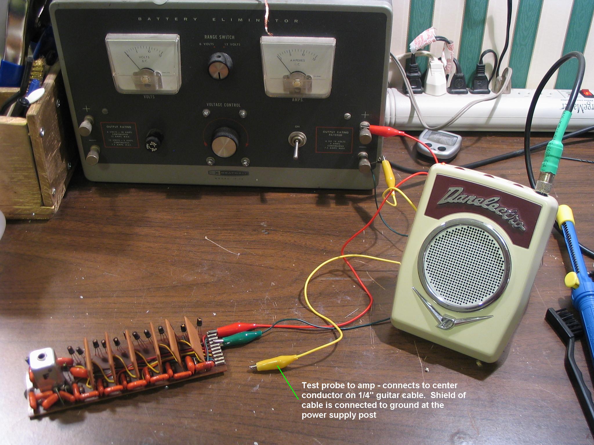
Many organs have plug-in oscillator boards that can be removed and bench-tested. All this involves is hooking up an appropriate power supply to supply DC voltage to power the board, and using a signal tracer to check the oscillator and divider outputs. This is easiest with boards that only need a single supply voltage. Make sure you observe the correct power supply polarity - UK and Italian Continentals, for example, use a negative supply voltage, in which case the + output from your power supply will go to Ground and the - output to the DC input. Some boards have the supply voltage connection point clearly marked - it may say "B+" or "Vcc" or simply "+". If not, you'll need a schematic or board diagram to guide you. Once the board is powered up, you can us a signal tracer to check oscillator and divider outputs to see where it's failing. If you don't have a signal tracer, you can make one pretty cheap and easy. Take an old 1/4" guitar cable you don't need, cut off one plug and strip the insulation back. Connect an alligator clip to the shield and a test probe of some sort to the center conductor. For the test probe, you can use a cheap meter test lead (get a set at Radio Shack for a few dollars) - cut off the banana plug end and connect it to the center conductor. For the alligator clip, you may want to use a foot or two of wire. This just gives you a little more room to move around when using it - especially when you're using it in the organ itself. Connect the alligator clip to the ground point on the board (again, it may be marked, or you can use a schematic or board diagram to guide you), plug the other end of the guitar cable into a guitar amp, Now, I must recommend that you use a cheap amp that you wouldn't mind parting with. I have never had any problems using this rig, but it's possible that if you accidentally touch the probe to a high-voltage point in the organ, that you may damage the amplifier (few organs have high DC voltages present, but the Gibson G101 does have a 100V supply for the percussion circuit). I use a cheap battery operated amp I paid $10 for. I advise you to find something comparable - DON'T use that expensive boutique amp or your precious 1960's Fender blackface or Marshall plexi!
Once it's all hooked up, turn the volume on the amp up just a bit, then touch the probe to the oscillator and divider output points (if the board isn't marked, use a schematic or board diagram to guide you). You should hear the tones as you touch each point. Start with the Oscillator output, and work down the dividers til you locate the culprit. If you get no sound at all, you may have a board with a bad oscillator - try it with a known-working board to verify that your test hookup is working properly.
Here are a couple of pictures of my Vox V301H generator board set up for bench testing. Here, I'm just using an alligator clip lead for a probe, but a regular meter probe with a pointed tip would be easier to use. (Click each picture to enlarge):
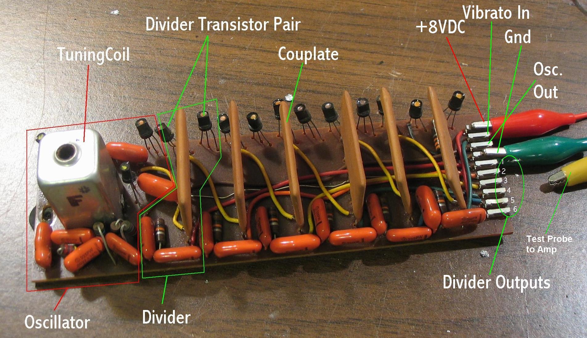
The "Couplates" shown in the picture are often called "resistor packs". They're actually collections of resistors AND capacitors.
Additional info for Vox Continental and Farfisa Compact fixes
Visit Dave Barraclough's excellent web site.Once there, click the Vox and Farfisa links on the left, then the Osc. fix links under those. He has some great info specific to those models.
The following about Farfisa Compact oscillators was provided by a fellow combonaut (Thanks, Bill!):
"A word of advice to anyone trying to troubleshoot one of these, don't forget to check the oscillator inductor coil windings for continuity. I had open windings on two of my oscillator inductors, I was able to repair them without rewinding the coils; but I used a microscope at work to do it. Also, you don't want to stick your meter probes into the eyelets on the coil when taking measurements, it's to easy to sever the tiny wires that are soldered there. To troubleshoot the cards I've found the easiest method is to unsolder the card from the harness and remove the card completely from the organ. I made up a test fixture to supply power to the cards from a nine volt battery with alligator clips soldered to the leads coming from the battery clip, connected to the + and - of the circuit card; it's not necessary to apply power to the vibrato input. Regarding the earlier discussions about faulty capacitors; capacitors will sometimes become leaky, allowing DC voltage into a part of the circuit where it's not supposed to be. Bridging a suspected faulty cap with a good one will do nothing to correct this situation. If a capacitor is suspect, it's best to remove it entirely from the circuit and replace it with a new one, especially if it is an electrolytic."
GENERAL PROCEDURE
Most combo organs have twelve oscillators, one for each note in the scale (A, A#, B, C, C#, D, D#, E, F, F#, G, G#). Each generates the highest octave, for it's note, that the organ is capable of playing. Lower octaves for the same note are created by one or more frequency dividers, one for each lower octave. Each divider takes the output from the previous stage, and divides it in half, producing the next lower octave.
You only have to tune each of the twelve oscillators - the dividers are not tunable. Normally tuning is accomplished via a variable inductor, or coil. It often is the largest single component on each oscillator board, usually situated near one end of the board. It usually looks like a can with a hex-key or screwdriver-head adjustment screw in the middle.
One large exception to this setup is the Melosonic/Whippany/Clark/Realistic line of organs, as well as the Magnus 3D Combo. You tune the oscillators on these with trimpots (they have little plastic thumbwheels with a small screwdriver slot in the middle), also located on the circuit boards. The trick with these is that each oscillator produces notes for three consecutive keys. So you just have to adjust for the best compromise of "in-tuneness" for each of the 3 notes.
Some organs, notably the Rheem Mark VII, use the standard 12 oscillators/divider setup, but for tuning use trimpots rather than variable inductors. They're easy to get to, right on top of the generator boards, but they can get dirty, and the tone may shift erratically as you try to tune them. Some spray contact cleaner can be used to clean them up.
Once you've found the tuning coil (or trimpot), you need to figure out which one is for which note. Sometimes they're marked, sometimes not. If not, you'll have to use trial and error - pick one and adjust it slightly back and forth, playing each note one at a time (you only need to cover one octave) until you find out which one you're adjusting.
Now that you know where the coils are, and which is which, you're ready to tune. It's probably a good idea to let the organ warm up a bit first - 5 minutes is probably sufficient. You'll need a chromatic tuner of some sort (one capable of tuning all 12 notes - 5-note guitar tuners will not do the job). If you have a PC handy, and can plug the organ's output into your sound card, you can use this excellent free tuner from Audio Phonics. Ideally, you should use a plastic tool to adjust the coil, but a metal one will do, it'll just be a bit more trouble. First, turn off all voice tabs, vibrato, and other special effects. Turn on ONLY one voice tab - the highest whole-number footage available (typically 2' or 4'). Do NOT use a 2-2/3' or other fractional voice. Find the highest 12 notes on the keyboard that will play (if using a very high footage, like 1', you may find that some of the uppermost keys don't sound), and use those to tune with. Play each note, one at a time, observing the tuner. Adjust the coil appropriately to bring the note into tune. If using a metal adjustment tool, you'll find that just bringing the tool close to the coil causes the pitch to change (although I've found that with Vox Continental oscillators, at least some of them, you can use a metal screwdriver and it doesn't affect the pitch). In this case, you'll have to make small adjustments, backing the tool off after each to observe the change. Keep doing this until the note is in tune, then move to the next. After doing all twelve, you might want to go back and re-check each one, tweaking any if necessary. At this point, it wouldn't be a bad idea to put a few drops of wax on the adjustment screw, to keep it from working loose. Most are pretty tight, and will stay put on their own, but it doesn't hurt to do this, just to make sure.
NOTES FOR SPECIFIC ORGANS
Farfisa Compacts & Mini-Compacts:
There are 12 tuning holes in the back of a Mini-Compact (one for each note). They're arranged as follows (facing the back of the organ):
B
G D#
A# F#
D
A
F C#
G#
E C
I've been told that the early version of the Mini-Compact (the one without the grey bass keys) does not use this arrangement, but rather the one used by the Compact (below)
On the Compact and Compact Deluxe, only the bottom 6 are accessible through holes in the back of the case. To access the top six, you need to remove the plastic top (two screws, one at either end). They're not in the same arrangement as on the Mini, however, but rather are set up like this:
A
C# F
E
G# C
B
D# G
F#
A# D
The Compact Duo has a small panel of trimpots to the left of the tabs when the top cover is removed. There's also a set of tunable coils accessible from the back.
Farfisa Fast 4/5
Underneath the organ, there's a plastic panel. Remove that, and the tuning coils are accessible from there
Kustom Kombo (The single-manual, NOT the Kombo II):
Grab the front edge of the tuck'n'roll top (just behind the tab panel), and lift up. You may need to use a screwdriver or butter knife to help it up (but PLEASE be careful not to damage the Naugahyde!). The lid is hinged, and lifts right up. Push it all the way up, so that the arm on the right locks to hold it in place. The generator boards are all in plain sight, and the tuning coils are at the back. There are only 3 physical generator boards, each with four generator circuits on it. You'll need a 2.5mm Allen wrench. Turning them clockwise raises the pitch, counter-clockwise lowers it. The boards are NOT in note order, but are clearly labeled, so pay careful attention - you don't want to wind up tuning your C# way out of pitch, thinking you're doing the C.
Yamaha YC-25D/YC-45D
Most of this is from my experience tuning my YC-25D, soon to be supplemented by my YC-45D. Your experience may vary slightly.
Remove the two screws securing the top These are underneath the organ, one on either side. The two closest to the back of the organ release the top. Lift the top up and find the oscillator board. If it's a transistor oscillator model, it will have 12 tuning coils on it. In the YC-20, it's mounted on the control board

On the YC-25D and YC-45D, it's in the card cage, the board closest to the pedal compartment. Remove the two screws securing the board. If it doesn't lift right out, but gets caught against the back of the cabinet, you may have to remove the two large screws securing the card cage, and nudge that end of the whole cage forward slightly, so the oscillator board will clear the back of cabinet. Be very careful of the wires. There are no dangerous voltages in this area, but you don't want to accidentally break one. You may also have to bend back the wire-tie securing the wire bundle to the front of the card, so that bundle can drop down the side of the card as you lift it out of the cage.
The oscillator coils are arranged as follows:
top of card, facing the coils.
| _ | _ | _
G D A E B F#
_ | _ | _ |
C# G# D# A# F C
If you're using a metal hex key, the pitch of the oscillator will drop about 5 cents with the key fully inserted into the coil, so tune it 5 cents flat, and it should be almost dead on when you remove the key
You'll need a 7/64" Allen wrench
Gibson G101/G201, Lowrey T2
G101: Remove the plastic top (four screws just above the keyboard, and one on each end). G201/T2: Remove the four screws on the wooden top and lift it up. The generator boards are along the back, and each one is clearly marked (if not, the left-most is C# for the G101, F for the G201/T2, and they proceed chromatically, left-to-right). You'll need a 2.5mm Allen wrench. Clockwise raises the pitch, counter-clockwise lowers it. Inserting a metal hex key will drop the pitch quite a lot, so it'll be an "adjust/remove/check" cycle until you get it right.
One of the most common problems with combo organs is dirty key contacts. That scratchy, crackling noise that the organ makes when first played after many years of storage is quite common, and fairly easy, although tedious, to remedy. Keep in mind that many organs have several contacts for each key - sometimes as many as nine! So you may be in for a LOT of cleaning (which is why I say it's tedious). Before you go to too much trouble, try just playing the offending keys - play them LOT. Take one finger of each hand and hammer on them repeatedly, one by one. I've found that just doing this will often clear up over half of your staticky, crackly keys. If you've still got noisy or non-working keys, then read on.
First you have to gain access to the contacts. Every organ is different - some are easy and some are almost impossible. Following the cleaning procedure, I've included specific instructions for various models
You also need to know which contacts are the offenders. Usually, there's one contact on each key for each footage of voices. For instance, if the organ has 16', 8' and 4' voices, there'll be three contacts per key, one for each rank(footage). There may also be an extra set for Sustain or Percussion keying. You may need to turn all of these features on to fully check out every contact on every key.
Cleaning Procedure
Tools: Pipe cleaners, Spray contact cleaner (get the "cleaner-only" kind, do NOT get "cleaner/lubricant". Lowe's sells a nice big 12oz can for about $6 - you'll pay twice that at the Rat Shack), pure isopropyl alcohol - don't use "rubbing alcohol" - it has other stuff in it that can gum up the works. You can get pure isopropyl alcohol at a drug store - ask the druggist.
Be very careful - the key contacts, while pretty robust, can be bent or broken if you're not careful. If this happens, it may be VERY difficult to repair.
Spend a few minutes pressing keys and observing how the contacts work, particularly the points of contact - these will be the areas you want to concentrate on. To start, especially if the contacts are difficult to get to, you just douse them with the spray cleaner, then play the keys a lot to work it in. This alone may clear up 90% of your remaining contact problems. If you still have some bad boys, isolate those and work on them individually with pipe cleaners and alcohol
Here's what combo-tech Kirk Slinkard has to say about cleaning:
"The best way to clean contacts I know of is to spray the bus bars with cleaner or alcohol then give them a good scrubbing between the bus bars using pipe cleaners. And get the moving contacts while you are at it. They always seem to just fit. Q-tips never seem to fit. Sometimes I soak the pipe cleaner with alcohol first and don't spray. The pipe cleaner always seems to get too dirty to continue using after covering the area of just a few contacts. A Denver area pro told me about the pipe cleaners, and they always seem to do the trick. She recommends playing every note on the keyboard for a while after cleaning."
Accessing the key contacts
I'll include a few models I can think of off the top of my head, and add more as time goes on:
Doric: Remove the three screws on the bottom of the organ, and lift the entire organ assembly out of the bottom section. The key contacts are easily accessible from underneath.
Howard: Remove the two large screws from the top. The lid (part with the tabs) is on hinges and lifts up. Then you can just lift the keyboard up (also hinged) and access the contacts from underneath.
Yamaha YC: There are two screws on the front, underneath the organ, that release the control lid, allowing it to swing up. There are two more screws, also underneath, that release the keyboard(s), which also swing up. Once they're up, there are several clear plastic dust covers covering each bank of key contacts. These just pop off with finger pressure. Don't forget to put them back on when you're done! NEW In the case of my YC-25D, I found the contacts covered by a long shroud made of egg-carton type styrofoam. It was pretty easy to pry out from under the wires and lift out.
Farfisa Mini-Compact: If you loosen the bolts which hold the power supply in place, then it can be slid inward, towards the organ. This will prevent the knobs from hitting the case in the next step. Then the case can be unscrewed so that, if the organ is set up on its legs, the case can be lowered to the floor, exposing the guts of the organ. Or, if you don't have the legs, you can lift the organ out of the case.
Farfisa Compact Duo power supply
GIBSON G-201 OWNERS NOTE: The G-201 does NOT use the same power supply as the Farfisa. They are radically different, in that the G-201 requires SEVEN different voltages to operate (the Compact Duo requires only one). You can obtain a free service manual for the G-201 by emailing relations@gibson.com but be forewarned - construction of a G-201 power supply will not be a trivial task - certainly not as simple as the one described here. I am in the process of constructing a power supply for my own G-201 (actually, it's a Lowrey T-2), and will publish information here after that project is done. Look for it in the Spring of 2003 (if all goes well).
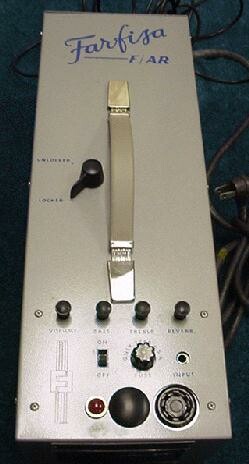
The Farfisa Compact Duo does not have a built-in power supply, nor does it have a standard 1/4" audio output jack. It does have a 1/4" jack on the bottom, but that's an audio output only for the bass section. It has a cable with a multi-pin plug designed to go into either the F/AR unit or one of the Farfisa amps designed for the Duo (the Transicord accordion uses the same setup) This plug has 7 pins on USA models, and 10 pins on European models. There is also a multi-pin jack on the bottom, with about 15 holes - that's for the bass pedals. The F/AR unit is a power supply, preamp and reverb circuit built into a small box that the multi-pin cable plugs into. Click here to see a picture of one.. It provides a standard 1/4" plug for audio output, as well as an input jack that you can plug another instrument into to make use of the reverb. It is commonly included with the Duo, but there are may F/AR-less Duo's out there. If you have one of these, don't lose hope. You have two options:
1) Find a used F/AR unit and buy it. I've seen these on Ebay from time to time, and they usually go for between $100 and $400.
2) Build a suitable replacement. Here's a link to a site where Dave, an enterprising Compact Duo owner, has documented his experience doing just that: How To Build Your Own Farfisa Power Supply
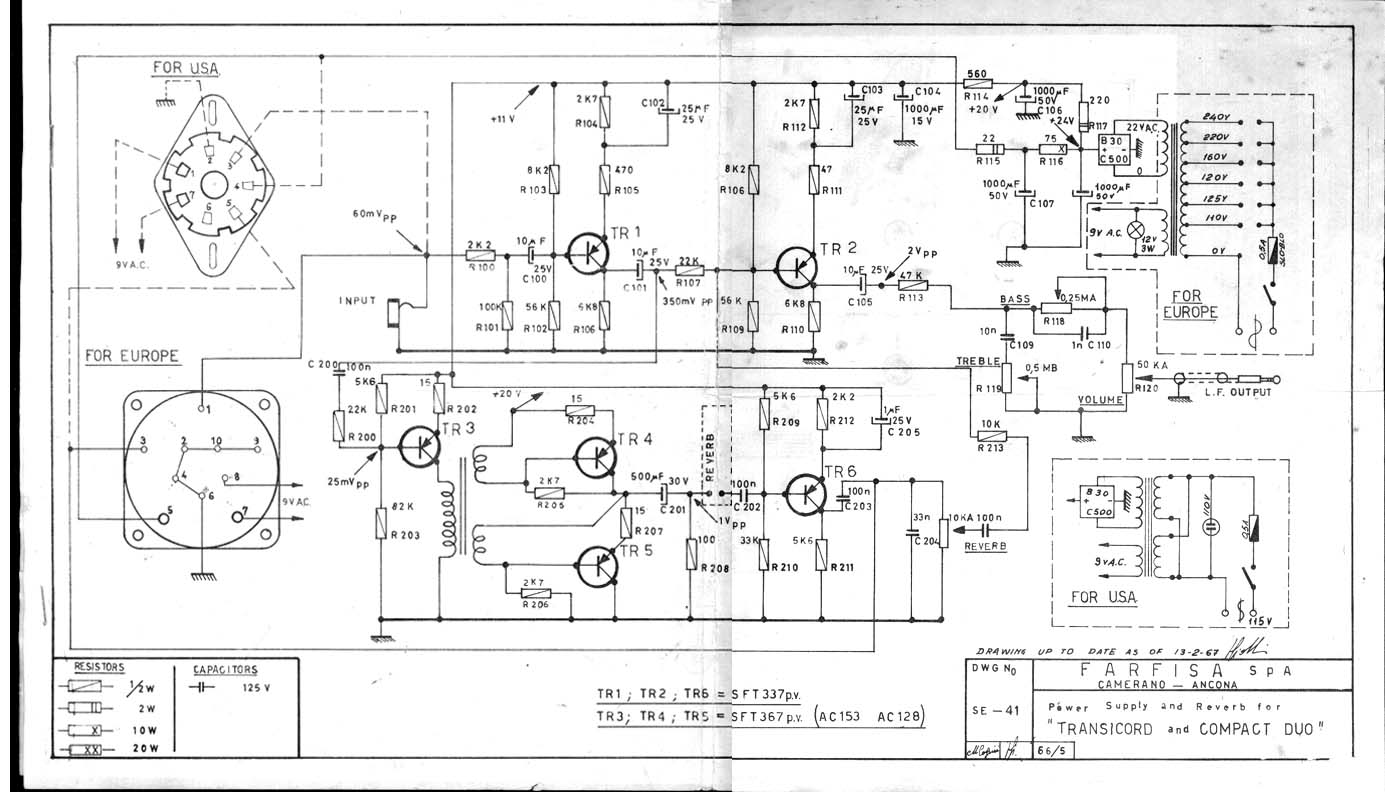
I've also been fortunate enough to locate a schematic for a F-A/R unit. Click here to get it. After reviewing it, I came up with the following table showing the functions of the various pins on both the USA and European connectors. The only things you really need are the 30VDC (see below) and the Audio out (the 9VAC out is only used to drive the light bulb in the volume pedal). If you can make a connection to the proper pins, just connect a power supply (probably about 500ma will do it) and a 1/4" jack and off you go. You won't have Reverb, but most guitar and keyboard amps have that anyway.
Pinouts
| Function | USA | Europe |
| 9VAC Out | 1 & 7 | 7 & 8 |
| Audio Out | 3 | 1 |
| 30VDC Out | 4 | 5 |
| Reverb switch | 5 | 3 |
| Ground | 2 | 2, 4, 6, 9, 10 |
Regarding the 30VDC power supply: The F-A/R supplies 30VDC (give or take a few volts) to the Compact Duo, but upon entering the Duo, the first thing it hits is a Zener diode, which regulates it to a steady 9VDC. So the 30V is only needed for the preamp and reverb circuit within the F-A/R. If all you're doing is building a replacement for the F-A/R to power the organ, then you just need 9VDC (or more). Probably the easiest and most effective thing to do would be use a 9V transformer, rectify and filter that to supply the DC to the organ, and take the 9V directly off the transformer to supply the. (when I say "transformer" here, I mean an actual AC transformer, not a "brick" or "wall wart" - those are complete power supplies providing DC at the output, not AC)
Where to get the connectors? You can get the plug that goes on the end of the organ cable from two different sources:
USA version: Looks like a 7-pin Leslie plug (if there is such a thing), but I'm not sure. Two of the pins are larger than the others. Ken's Electronics used to carry them (part #86P7), but he no longer has any and hasn't been able to find any more. He does have the female socket, however - ask for part #78S7 I'm not 100% certain that this is the correct part, but it looks like it would fit, and it's cheap (about $3, I think), so it's worth a chance. If you buy one of these and it fits (or doesn't), please contact me and let me know, so I can update this page Update!: Thanks to Ryan for finding these, both male and female, at Halfmoon Electronics. They're a little pricey, but if you need 'em, you need 'em! There are other plugs on that page, but the ones you want are at the bottom - the 7-pin Amphenol connectors
European version: Hirshmann makes the correct connector. Their part number is MES-100 (order # is 973017100). They don't sell direct to the public, but one of their distributors referred me to Major Electronics (440)942-0054. They supposedly sell small quantities at the retail level. You can also check with Beckwith Electronics - their price is $8.50 each, but they have a $25 minimum order. If you're in Europe, contact Electrospeed, at 02380 644555. Sadly, Hirshmann no longer makes the MES-100 or MEB-100, and Beckwith has no more in stock, either. If anyone sees this, and knows of another source for these connectors, please contact me. Thanks.
Gibson G101/G201 and Lowrey T2 Percussion/Repeat circuit problems
Probably the most commonly reported problem with the Gibson G101/G201 (and Lowrey T2) organs is a non-functioning Percussion/Repeat circuit. The most common reason for this is failure of the neon bulb that's in the heart of this circuit. Here's a really crude block drawing of how it works:
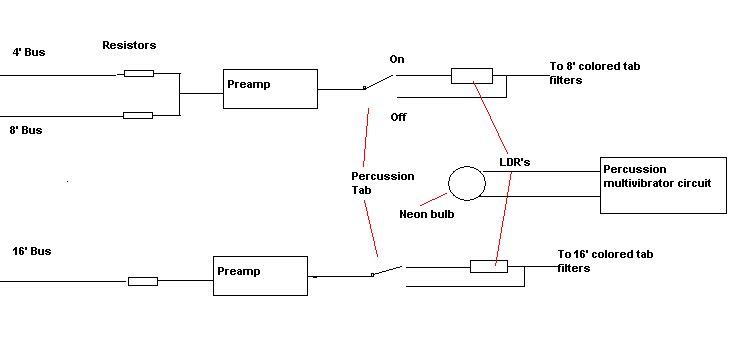
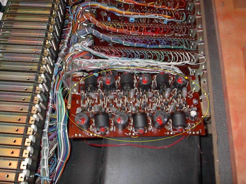
The neon bulb is driven by the Percussion multivibrator circuit, which causes it to light up then fade out quickly. The Repeat switch modifies the function of the circuit so the bulb does this repeatedly. The bulb shines on the LDRs (Light Dependent Resistors), causing the signal to the colored tab filters to follow the brightness of the bulb, causing a sharp Attack then decay. If just one of the LDRs fails, the Percussion/Repeat will work for only the 16' or the 8' colored tabs (note that the 8' colored tabs are actually a mixture of 8' and 4'). What most commonly happens, though is that the bulb darkens with age, so it can no longer affect the resistance of the LDRs. Replacing this bulb will solve the problem. Here's a picture of the neon bulb/LDR assembly, partially disassembled:
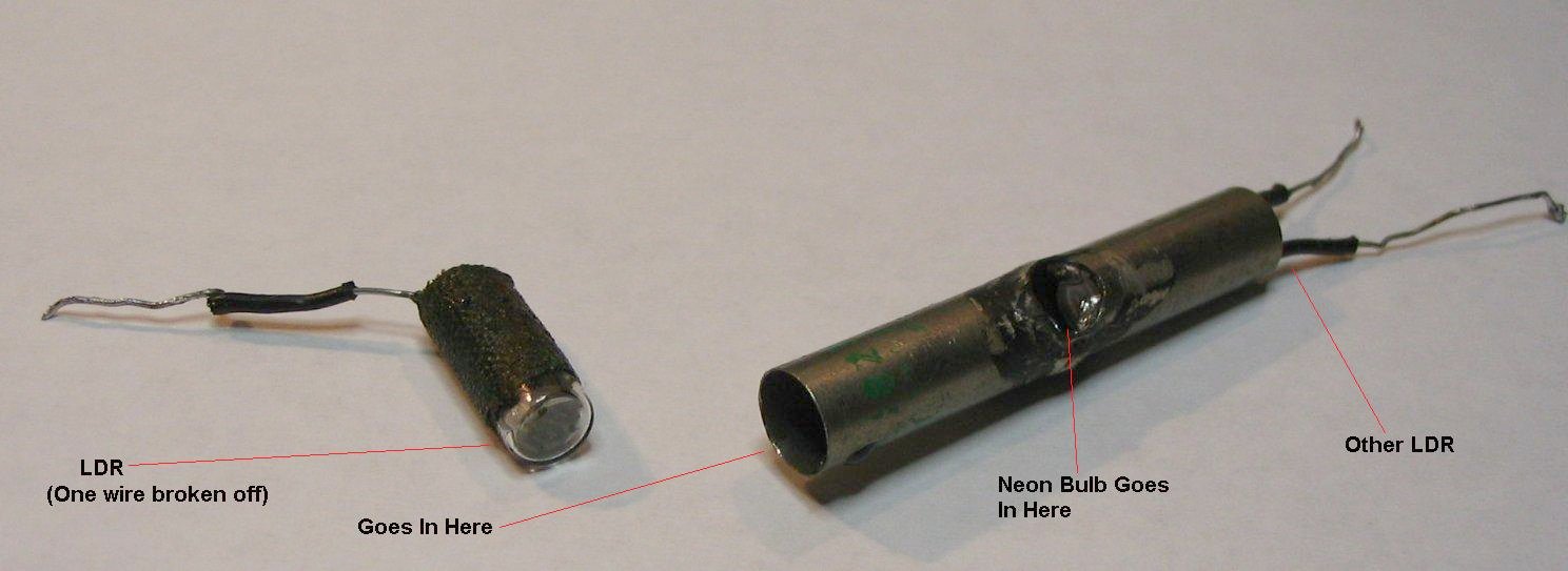
This assembly is soldered to the circuit board under the Percussion tab. If you measure the voltage across the neon bulb, you should see the effect of switching on Percussion and Repeat (the peak voltage is about 100VDC, so be careful!). If the voltage appears to be changing as it should, but you get no effect, then the bulb is probably shot. To remove it, you've got to scrape away the opaque gunk that's used to cement it into the metal tube. You may have to completely demolish the bulb to do this. Be careful - the faces of the LDR's are very close to the bulb. Clean out any remaining gunk (and pieces of glass), put in a new neon bulb (Get the kind with wire leads attached), and seal it in place with some sort of opaque glue. JB Weld comes to mind. Make sure to cover the entire bulb.
Neon bulbs available at Radio Shack do not appear to be able to handle as high a repeat rate as the stock bulb, I have, however, found a replacement bulb at All Electronics Part# NE-2E / A9A, 10 for $2.75 (Thanks to Alan L for the updated part info). This bulb tracks the repeat circuit perfectly. Any breakup of the pattern at high speeds is probably due to the multivibrator circuit itself. I put mine on an oscilloscope, and it was the signal driving the bulb, not the bulb itself, that caused the pattern to "stumble" at high speeds.
The LDRs have a resistance in total darkness of about 2megohms, and in bright light of about 200ohms. Radio Shack carries a pack of assorted LDRs, part# 276-1657, $3.19 (another thanks to Alan L for the updated part info). I don't know if it's always the same assortment or not, but mine contained three large LDRs and two small ones. The small ones fit nicely in the metal tube. One had orange marking and the other had black markings. The orange one had the proper characteristics, so I used it. I stripped some insulation from another wire and fitted it down over the leads. Then I wrapped it in duct tape until it fit tightly into the tube. I used one of these to repair the percussion in my Lowrey T2, and it works perfectly.
Click here for an excellent PDF explaining
how to replace the bulb in the LDR assembly (494KB)
(Thanks to Nate Christian for this one)
Below are some closeups of the bulb/LDR assembly and wiring board from my Lowrey T2. A Gibson G201 would be the same:
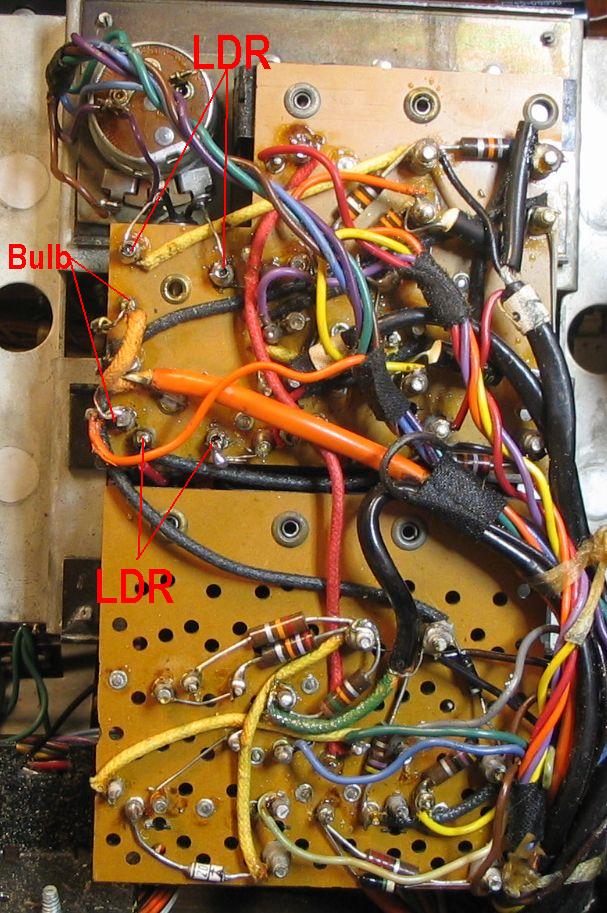
Underside of the board, showing the connection points |
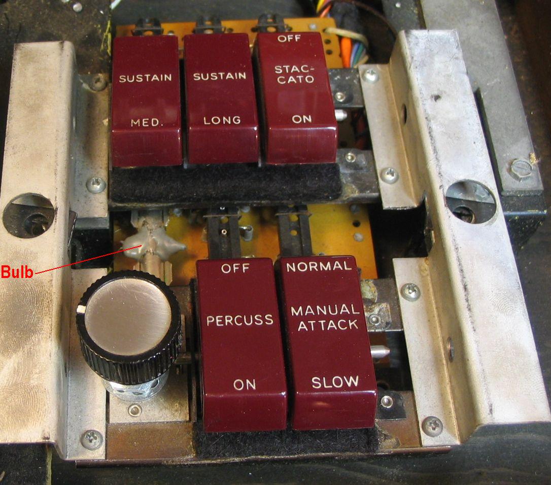
Top of the board with the panel removed, showing the location of the bulb/LDR assembly |
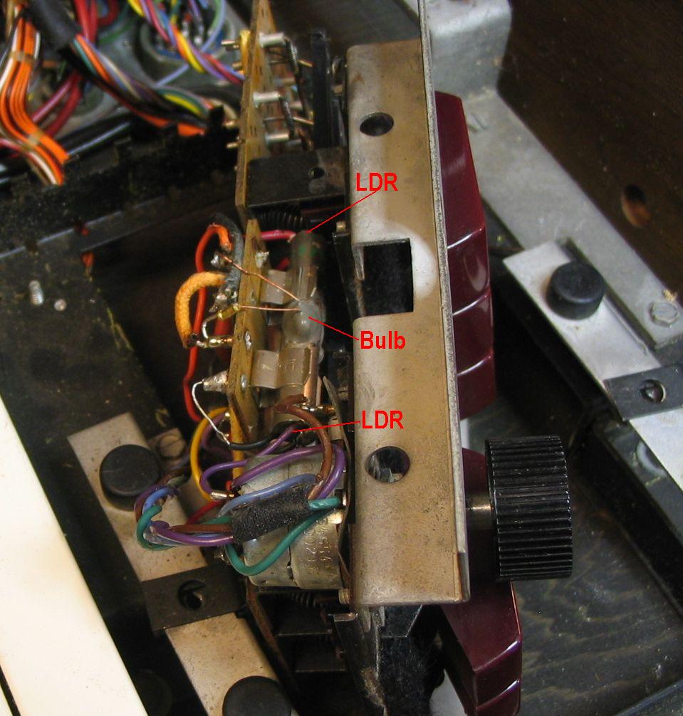
Side view of the board, showing the how the bulb/LDR assembly is attached and wired in |
If you have no output at all from your organ, it could be because you don't have a volume pedal. The following organs normally will produce no output without the correct volume pedal attached: Clickable links take you to information about the associated pedal:
Fender Contempo
Gibson G101/G201, Kalamazoo K101
Lowrey T1/T2
Rheem Mark VII
Most other organs, included every Vox and Farfisa model I know of, do not require a volume pedal to function.
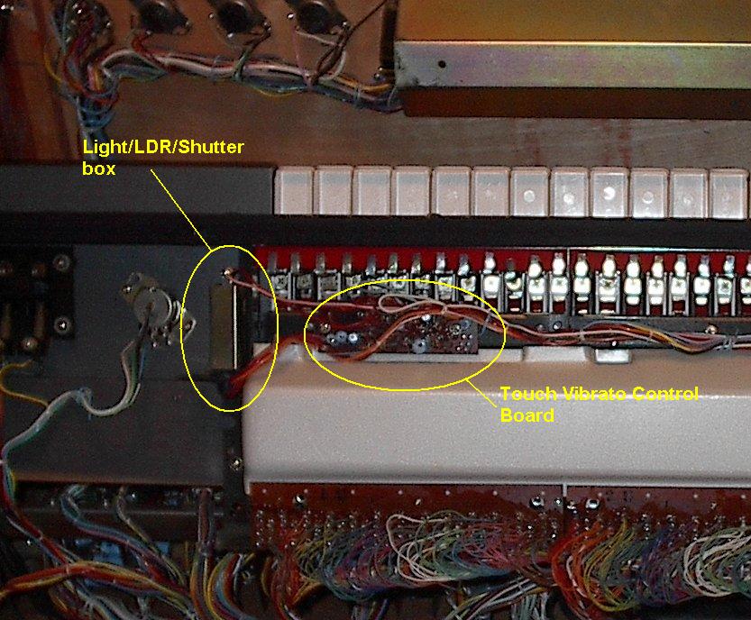
Yamaha YC-series touch vibrato
The touch vibrato mechanism consists of a long flexible metal strip under the keys that actuates a "shutter" in a small box to the left of the keyboard. The box contains a light bulb and a photo-resistor (just like many volume pedals), and movement of the shutter varies the amount of light that's allowed to hit a photo-resistor, which varies a voltage that's applied to a control input to the oscillators, producing a pitch change.
The first thing to check is if the light bulb in the little box is burned out. You should be able to see light escaping from it. If not, open it up and check the bulb, and replace it if necessary. The bulb shroud is just held in place by a couple of rubber nubs, one on either side - pry the shroud slightly outward on one side, and work it toward you gently - it should slide right off.
If the bulb is lit, then try wiggling the shutter by hand. If the pitch wavers when you do that, then the circuitry is fine, and it may be the depth adjustment. This is a trimmer pot on the touch-vibrato circuit board. It's a small board, about 1" x 3", located just to the right of the light bulb assembly. Turning this pot to the right increases the depth, to the left decreases it. If you can't get a suitable effect by adjusting this pot, go on the the next step.
If wiggling the shutter by hand (which will probably move it far more than the keys would) then the mechanics that are bad (see next paragraph). If the light is on, and wiggling the shutter does nothing, then there may be dirt or some other obstruction inside, preventing light from reaching the photo-resistor, or there may be something wrong with the circuitry. If it's the latter, then you will need a service manual and someone more experienced than me to fix it.
If you can waver the pitch by manually moving the shutter, then you
need to figure out why the keys aren't moving it properly. One thing to
check is if when the shutter moves (from the movement of a key), is the hole
being exposed more and less. If the shutter isn't moving at all, go to the
next section. If it's moving, you may need to adjust the amount of the
hole that's being exposed as the key moves. Loosen the bottom screw to the left of the light bulb, and
nudge the assembly one way or the other so that when the keys are at rest, only
a tiny triangle shaped hole is exposed, and when a key is moved to the right,
that triangle grows in size (in my experience, it's the right-ward key movement
that makes the greatest change - moving the key to the left doesn't move the
shutter as much). You may have to play with this a bit. If you're
careful, you can nudges the shutter assembly by hand while you wiggle a key
(make sure you have the Touch Vibrato or Touch Mute turned on!), adjusting for
maximum effect. When you have that, carefully tighten down that screw,
then replace the bulb shroud.
If the shutter doesn't move when a key is wiggled, the strip running under the keyboard is messed up somehow. The metal strip has a felt strip glued to the top, and it sits atop a foam rubber strip. Little pointy things under each key "grab" the felt strip and allow the key movement to move the metal strip. In my experience, the glue that holds the felt strip on had dried up, and the keys were moving only the felt. Get some glue suitable for binding cloth to metal (I used a form of silicone rubber) and re-attach the felt strip. To do this, you'll have to remove pretty much all of the keys. The next section explains removing the keys.
Removing the keys:
You may have occasion to remove a few keys, or perhaps all of them. For instance, to just give the whole keyboard a good cleaning, or to get at the entire touch-vibrato strip for cleaning and re-gluing.
Lift the keyboard up. Each key is secured by an L-shaped bracket fastened to the underside of the key. Unscrew the screw holding the bracket to the key, but don't unscrew it entirely (you can, but it's not necessary) - about 3 turns will loosen it enough to rotate the L-bracket 90 degrees so it will clear the bar underneath the keys, allowing the key to rise up. Don't let it fly up, or the spring will come loose and you may have trouble finding it. After the key raises up, you'll see that the rectangular slot at the opposite end is nestled into mating stubs in a long rubber strip at the back. Carefully lift the key up and back, off the rubber stub (I'm making up these words as I go along), then gently down so the spring comes loose from the bottom of the steel bracket that supports the keyboard. Remove the key, being careful to keep the spring and L-bracket with it. It's probably a good idea to keep all the keys, springs and brackets together and in the same order you removed them - they're probably interchangeable (i.e., any "C" will fit in any "C" position, except, of course the very top one), but not worth taking chances. One thing I did note: the black keys have black springs, and the white keys have silver springs.
To replace the keys, just reverse the procedure. With the spring hooked to the key, hook the other end to the steel bracket, settle the notch at the back over the rubber stub, lower the key down, with the L-bracket rotated to the side, until it clears the bar under the keys, then rotate the bracket forward under the bar, which will hold the key in place. You can put all the keys in like this, then lift the keyboard up, and tighten all the L-brackets down. The key end of the bracket fits into the key nicely, but it helps to reach around and push the key slightly toward you when tightening it, so it settles in properly and isn't skewed. The only tricky points are around some stabilizing bars located about one per octave - you'll have to wrestle with it just a bit to get the L-bracket around this, and the keys at the far ends can be a bit difficult - long-nosed pliers are a help there. If you do this carefully, the keyboard will be just fine when you're done.
If you have keys that have become skewed or sit higher or lower, it may be the little key guides under each key - these are wrapped with red felt, and are what stops the key when you press down on it. Check to make sure they're straight and even - if not, carefully bend as needed to bring back into line.
Vibrato doesn't work or is too fast/slow
If it doesn't work for ANY of the notes, then the vibrato circuit is at fault. Check the switches that control the Vibrato, and clean the contacts. Check the vibrato circuit board for burned, loose or oozing components. If it all looks good, check any electrolytic capacitors that may be there. See "Checking Electrolytic Caps". If the vibrato works for most notes, but not for some, then you've got a loose or broken wire between the vibrato circuit and the oscillator boards. There is a single wire that delivers the vibrato signal to each oscillator, so it should be pretty easy to trace. If you have an oscilloscope or even an analog voltmeter, you'll be able to find it (on a working board) by looking for a low-voltage signal that wavers slightly and rhythmically. (this would be very hard to pick up with a digital voltmeter).
Vox Jaguar vibrato speed adjustment: "There should be a 5K trimmer
potentiometer on the LOW C DIVIDER/VIBRATO OSCILLATOR circuit board.
That is the vibrato speed adjustment. It will be the only trimmer on
that circuit board." (thanks, Kirk)
Next to dirty switch contacts, electrolytic capacitors are probably the single primary cause of most combo organ circuit failures. Electrolytic caps just go bad over time, even sitting on the shelf unused. When they get really bad, they will burst or ooze gunk, so they're pretty easy to spot. But even if they look good, they can be either totally bad, or so for off-value as to cause circuits to do strange things. Power supplies are heavily affected, because they usually use two or more very large ones. Because electrolytics often drift toward being an open-circuit when they go bad, they can be fairly easy to test without removing. To test a cap in-circuit, just get a new one of the same or slightly greater value (for both voltage and capacitance), and use a pair of alligator-clip test leads to connect it in parallel with the existing one. MAKE SURE YOU GET THE POLARITY CORRECT! I've never witnessed it, but I've been told that electrolytics connected backwards can explode! If you aren't reasonably comfortable working with electronic components, you should probably not attempt this. If the cap in question is the culprit, then the symptom may disappear. However, sometimes caps will become electrically "leaky", becoming more like a short circuit rather than an open one. In this case, simply paralleling a new one will NOT fix the problem, you'll have to cut one lead on the existing one, then connect a new one in it's place. When replacing caps, always get one of at LEAST the same voltage rating - higher can never hurt, and might even help increase the longevity (so your grandkids can have fun with "gramps' old Farfisa"). As far as capacitance, also get at least the same value or greater. In power supplies, more is usually better, so replacing a 500uf cap with a 1000 will not hurt. In other circuits, the value may be more critical, so try to get as close as possible. For instance, if you need to replace a 50uf cap, but only have a 47 and a 100 available, the 47 may be the better choice. Electrolytics are cheap, even at Radio Shack, so you could experiment a bit if you like - you might wind up with a very fast/slow vibrato, or a very long/short sustain or percussion circuit.
Organ makes a constant whiny racket, or growling noise when any key is pressed
Most combo organs have a sort of whiny, ringing din going on in the background. This is the sound of all the oscillators and dividers at once (like pressing all the keys at once). A certain amount of this is normal (and seems to be more prevalent in Farfisas, for some reason). But if it's loud enough to be heard over normal playing volume, it could be one of two things - a loose ground connection, or bad electrolytics in the power supply. A loose ground connection might be anywhere, so check for wires that are obviously disconnected, and gently poke and prod other wires, especially shielding and wires that clearly connect to parts of the metal chassis. Check on the electrolytics using information in the preceding paragraph. Another sound that can be caused by bad power supply electrolytics is a growling sound when any key is pressed.
POWER CORDS!
One of the most-often requested items is a replacement power cord. Back in the 60s, the IEC-style "computer" power cord was not common like it is today, and there was a plethora of incompatible cord styles. These days, most of those styles are difficult, if not impossible, to find. For those of you who haven't already replaced your power socket with an IEC standard one, you may find what you're looking for here. If you find one that fits, and your organ is not listed here, please Contact me and I'll add it to the list
Below is a table showing some I've found and some organs they're known to
fit:
Measure the pin spacing on the receptacle on the organ. Measure
center-to-center, then find the one that fits you best:
| Pin Spacing | Organ(s) | Link | Notes |
| 5/16" | Rheem Kee Bass Rheem Mark VII |
Basic 6' cord in brown at Amazon Nice 6' cord in RED! (scroll down a bit) White 6' cord at Ace |
Also known as a "cheater cord", used by TV repairmen to defeat the interlock that prevented the TV from powering up while the back was off |
| 1/2" | |||
| 11/16" | |||
| 3/4" | Howard, Doric |
Farberware percolator cord (only 3ft long) eBay: Check out seller "westcoastresale" for a 6ft cord for about $14 |
3/4" spacing is hard to find - none at Amazon or Ace that I could find. You can usually find them on eBay, listed as "Vintage percolator cord", and the prices tend to hover around $20-$25, but occasionally you'll turn up a more reasonably priced cord. Pay attention to cord length, often they're only 3ft. Not a huge problem, just get an extension cord. |
| 1-1/16" | |||
| US-style | Vox Continental V301H(US) Elka Panther Combo Elka Panther 100 |
Old-style 2-prong (US) "lawn mower" extension cord There's also a 25-ft version. May need the "ears" trimmed off with a utility knife |
If you don't find what you want here, try these search words in your favorite search engine:
Appliance cord
Woods appliance cord (Woods makes several of these)
HPN appliance cord (I have no idea what 'HPN" stands for)
Percolator cord
Add the desired pin spacing (i.e. "3/4" spacing") to any of the above terms to narrow things down. You should find several hits at Amazon, Wal Mart, Ace Hardware and who knows where else! Ebay is also a good place to search, lots of vintage-style cords there.
MORE LINKS TO PARTS AND STUFF:
Vintage Planet: parts for vintage synths, but probably some useful combo parts there, too
Vintage Vibe: Chris has lots of great information, parts, etc for Vox organs (as well as Wurli and Rhodes pianos). Drawbar tips, latches, hinges, bias pots, transistors, keys and more.
Vox Orange Vinyl: Carefully researched and matched for his own needs, David Robertson has graciously made available his remaining vinyl, precut in pieces large enough to cover one Continental red top. This vinyl is a far better match than you're going to find anywhere. The link to the left is to a PDF with some high-quality photos, showing this vinyl compared with actual vox vinyl, as well as some commercially available amp coverings. You'll be amazed at it's accuracy! The PDF also contains contact information for David. Hurry, quantities are limited...seriously! (date posted: 5/6/2011)
Roy J. Tellason: Roy has a TON of manuals available! Mostly NOT combo organs, but there are a few there, some Farfisa and Yamaha manuals are available, and probably a few others I've missed. There are also manuals for a plethora of other electronic devices, so browse around a bit. Make him a decent offer one one, and it'll be yours. Roy also has a lot of electronic parts available at his parts-index page: http://www.classiccmp.org/rtellason/parts-index.html
User Manuals.Com: They sell PDFs of owners and service manuals. I haven't perused their stock extensively, but they do have service manuals for a couple of the Yamaha organs. If you run across any other good combo manuals there, let me know.
MAJ Electronic They have lots of parts and stuff for guitar amps, but they also have a few schematics for Vox and Farfisa combos. Email them, they may have what you're looking for.
Manuals-In-PDF.com Hidden among their extensive listings of manuals for modern appliances and electronics are manuals for several GEM and Farfisa organs. The Farfisas are listed under "FARFI". I think they charge $14.95 for every manual.
Swain Electronic Services(SES): Parts for Vox organs, including hard-to-find stuff like coils, transformers, boards, power supplies and complete drawbar assemblies!
Danelectroid! : Parts, like amp knobs, pots, jewel lights, etc, plus high-quality copies of original manuals, including a better copy of the GIbson G101 service manual than the one you get free from Gibson, as well as schematics for the MCI B300/B35 Guitorgan.
Mark Glinsky's Manual Manor Manuals for all manner of electronic musical instruments, amps, etc.
North Coast Music Parts, manuals and schematics for Vox organs - even "Z" stands!
Bulgin power connectors for UK Vox Continentals can be had at Angela.com
Allen Organs Parts for RMI keyboard products, plus some others.
Tolex Good source for this elusive, but oh-so-necessary substance.
Guitar Parts has a nice selection of parts for Fender, Gibson, Marshall, Vox and others. They have Vox amp handles, which would probably do nicely for Vox organs, but most interesting is their selection of coverings, including a nice black Tolex, and and even nicer Vox/Hiwatt black covering that looks very much like some early UK Continentals. Also, check out the Orange Basketweave - boy, now that would make an interesting material for a Vox organ project, but at $60/yard - yikes!
W.D. Greenhill & Co.. Parts and manuals for Elka, Baldwin, Lowrey and others. The only source for Elka manuals that I know of.
Melbourne Music Owners and service manuals for lots of musical instruments and audio equipment. Several combo organs listed.
Music Manuals: Fairly extensive collection of owners manuals, service manuals and schematics. A fair number of combo organs included in the list. Prices seem quite reasonable, too. Note that they prices are in British Pounds. They take PayPal, too!
Yamaha Owners Manuals.: Owners Manuals are available free, for downloading, at the Yamaha Manual Library. You can also call them at 888-892-6242. Photocopied owners manuals are FREE.
Yamaha Parts Service Manuals: Yamaha has sold off the parts and service manual business. They are now available from NTS Pro Audio 714-901-7222. As of 3/26/04, They have the following manuals in stock, for $25 each, plus shipping:
YC-10, part # C-SM-88
YC-20, part # C-SM-89
YC-30, part # C-SM-91
YC-25D, part # C-SM-90
YC-45D, part # C-SM-92
They tell me that these are original copies, and that once they're gone, they won't be reproduced. They also have a supply of parts, but I think most of the difficult-to-find parts (IC's, tone levers, etc) are long gone.
You can also get some of the YC Service Manuals in PDF form from User Manuals.Com When I checked, they had the one for the YC-30 and YC-45D, for only $14.99 - not a bad deal, if you don't need the paper manual. They also sell PDFs of the Owners manuals for $9.99, but that's kind of silly, since Yamaha gives them away for free. I can't vouch for the quality, because I've never seen one.
Yamaha A-3 Volume Pedal connectors: Many thanks to Scott for the detective work on this one. An exact replacement can be obtained. Quoting Scott: "... the connectors are made by Hirose, from the HS (Hirose Standard) Traditional Connector Series. The legacy part number is HS21P-5, but the nomenclature has been updated for RoHS to HS21P-5(71)... I was able to obtain the plugs from Brevan Electronics in New Hampshire; fortunately there was no minimum quantity or dollar amount. (btw, excellent customer service and lightning-fast shipping: www.brevan.com )"
Gibson Service Manuals: G101 and G201 manuals can be had for FREE by emailing them at relations@gibson.com. These are photocopied manuals, but quite readable. They contain complete schematics and some photographs showing the organs in various states of disassembly.
Gibson G101 Key Contact Rail Bar: Contact Schweineorgler@web.de He can supply the rail, you'll need to drill the small holes for attachin to the organ.
Farfisa: I have this address and phone number. I haven't tried calling them, but I wrote a letter, and several weeks later received photocopies of two different manuals - free of charge - such a deal!
Comus Farfisa S.R.L.
c/o Mr. Onofri or Mr. Fiodormo(English spoken)
35, V.S.G. Bosco
62018 Potenza Picena (MC),Italy
Phone: 011-39-0733-8851
Fax: 011-39-0733-885490
Knobs: No, not volume/tone knobs and the like, but the kind you use to attach stands, etc. This place has almost every conceivable type of knob with your choice of screw/bolt size and threads: Monroe Engineering
Knobs: Yes, the volume/tone type knobs. Cosmo Corporation makes the knobs used by Kustom, Moog and Rickenbacker, and STILL makes them! Plus a whole lot of other knobs - peruse their online catalog and you may just find what you're looking for (or a suitable substitute,anyway!)
Cables: These guys say they can make any cable to order: Expert Audio Repair Service (E.A.R.S) 547 West 27th, NY 10001 212-868-HELP(4357). I've heard from a few people who've had dealing with them and their experiences were uniformly excellent. I've also got them listed below in the "Repairs" section.
Wurlitzer Morelock's Organ Parts has service manuals and some other parts for the Wurlitzer 7300, and tons of other Wurlitzer's including their electric pianos. They have the 7300 power cord, which fits, but they also sell replacement oscillator coils, which, I'm told by one 7300 owner, do NOT fit and can not be made to work, so be careful.
Morelock's Organ Parts. Mark Morelock, Owner.
37-A Main Street
Reinze, MS 38865
Phone: 662-462-7611
Fax: 662-462-7611
Wurlitzer 7300 information: Bob Klossner: https://wurlitzer7300.com
Various Schematics: Pat's Tube and Recording Schematics Lots of schematics and advice available. He has Clavioline schematics, but no other keyboards. Still, it makes for interesting reading if you're into DIY and repairs.
Assorted hardware: Handles, latches and other interesting stuff is available at fliptops.com Their primary purpose is parts for old Ampeg amps, but several of the parts are similar to those used on some combo organs;
Case hardware: Handles, latches, hinges, etc, available at Ohio Travel Bag
More case hardware!: Visit Spike,
the Hardware Elf, to find lots of REAL reasonably priced case hardware
Examples: Vox latches - exact replacement, including
the "keeper" piece: L-032
Vox hinges: exact replacement: M-067
Elka (and other) latches: L-025 (Locking version, L-020
Vox Schematics: www.voxamps.co.uk Schematics are available here for the Continental 300, Corinthian and Continental II. Check in the Support/Service section. The quality isn't great, but they're fairly useable.
Banzaieffects: Pots with gears for volume pedals, rack gears, rubber feet, corners, knobs, lots of neat stuff.
Various Parts
Vox Continental bias pots: There's a UK seller on eBay that sells a set of 12: https://www.ebay.com/itm/157442640712. You can also buy them individually at Mouser:
Baldwin BC-1 power cord: A fellow combonaut found a cord for an Argus slide projector that fit his BC-1 perfectly.
Kustom Kombo pilot light/jewel: www.tubesandmore.com Pretty much an exact replacement, and WAY cheaper than the ones at Vibroworld.
Kustom Kombo ball caster: Lowes has them, but only in brass. About $7.50/pair. They look great on a Gold Kustom. The mounting plate is just a bit thinner than the original, so you have to reverse the screws - email me for details. You can get them in chrome from www.grainger.com, but you have to be an actual business to set up an account with them (and they're a bit pricier).
Kustom Kombo Knobs: Small Bear Electronics carries these: http://www.smallbearelec.com/Detail.bok?no=739 Cost is only $1.20 in single units, with discounts starting at only quantities of 10. They're the same knobs used on all the early tuck-and-roll amps (but not the early 70s slant-front amps - those are smaller) These are also the same knobs used by Moog synthesizers and Rickenbacker guitars (they're unmarked, though, like the ones from the mid-70s on)
Gibson G101 feet: (a bit smaller than the originals, but they work fine: www.tubesandmore.com, Part# P-H2082S
Gibson G101/G201 handles: www.fliptops.net Hand#5 Ampeg black plastic suitcase style handle
Gibson G101 knobs: A close substitute is at All Electronics, Part# KNB-40. It's a bit smaller, and has a brass insert, but if you replace all three at once, they look pretty nice. At 4 for a buck (plus $6 per order for shipping!) you can't beat 'em!
Gibson thumbscrews: The Gibson and Lowrey organs use 10-32 thumbscrews to fasten the dropdown panel to the legs, and to the organ when it's packed up. I found a couple of real nice ones at Ace Hardware for $2 each. Ace has an excellent selection of hard-to-find hardware.
Gibson circular connectors: These are available at www.mouser.com. They run about $10-$20 each, plus shipping. I found the power plug on eBay pretty cheap, and also saw numerous other Amphenols there, so set up a search and you'll probably find one eventually.
G101/G201/Lowrey T2 Volume pedal: Amphenol 97-3106A 14S-5P
G101/G201/Lowrey T2 Bass Pedals: Amphenol 97-3106A 20-27P
G201/Lowrey T2 Power supply: Amphenol 97-3106A 22-14S
In Amphenol part numbers, 3105 means straight plug (3108 is angled), the "A" means solid backshell, "B" means split backshell. the next number is the shell size, the next number is the insert arrangement, and the last letter, "P" means pins (male), and "S" means socket (female). The "MS-" series is the Mil-Spec version of the "97-" series, but are entirely compatible, so substitute "MS" for "97" and it should work fine: This PDF at Mouser explains it, and this PDF at Mouser shows all the relevant part numbers
Gibson G101 Power Supply connectors
It takes two: one 5-pin and one 9-pin. You'd probably only need these if
you were building a power supply for a G101, or a cable to run a G201 or Lowery
T2 off a G101 power supply. They are obsolete Amphenol connectors: 86CP5
and 86CP9 (plugs), 78S5, 78S9 (sockets). I believe these are identical to
the 5-pin and 9-pin Leslie connectors. A good, inexpensive place to get
them is Leeds Electronics
Gibson/Lowrey organ parts: Apparently, the Gibson and Lowrey combo organs used a lot of the same parts as the Lowrey home organs from the same period. These can often be had cheap or free. Many of the tabs, circuit boards, power supply parts, etc are the same. Check thrift stores, Craigslist and even eBay. I've also heard that the "Zachary Enchanter" organ uses the same keyframe as the G101.
Bulbs: Don's Bulbs has a huge selection of different bulbs. Only downside is the $40 minimum order. So go in with some fellow combonauts and lay in a supply for the future!
Handles: Brettun's Village Suitcase Handles Several different styles, many are probably close, if not exact, replacements for some combos.
Rheem panel plastic: www.precisiondrum.com sells drum recovering material that's similar to what Rheem used on the panel of the Kee Bass and Mark VII organ. It's not cheap, though.
Rheem Volume Pedal plug/socket: This round, 4-pin "Y" plug is a bugger to find. It's apparently the same kind of plug used for mics on old Lafayette and Courier CB's. The plug can be obtained from Ken's Electronics, part# CBC4Y. Ken may also have the panel-mount socket, part# CBC4YPMS, but it's in limited supply, and may not appear on the website, so contact him first.
Rheem Power Cords: Both the Mark VII and Kee Bass use the equivalent of what used to be called a "cheater cord" by TV repairmen. (The name comes from the fact that it enabled the repairman to "cheat", and power up the TV with the back removed). You may be able to find one at a TV repair shop (the kind that actually repairs TV's, not the "repair dept" at Best Buy). You can also sometimes find a matching cord on some small appliances. I found one on an old GE hand mixer, and a friend found one on a new electric knife. Check the thrift stores. You can find receptacle (for those of you who may need to replace it as well) at www.tubesandmore.com. It's part # P-SP2-K-002
Rheem Vinyl covering: The black vinyl covering appears to be standard, pebble-grain Tolex. It's available at Parts Express, part# 260-760.
Rheem Mark VII rubber feet (the organ has 8 altogether): Larger and sturdier than the originals - very nice www.tubesandmore.com Part# 5.31P-H9107
Power cords for Vox, Doric, Howard, etc: An oft-requested item, these are virtually impossible to obtain. You basically have four options:
1: Replace the cabinet jack with a standard IEC
connector. Functional, but offensive to many vintage gear enthusiasts
2: Visit a thrift shop and peruse the coffee pots, waffle irons, etc. You may
find one with a connector that fits just fine, or at worst, will require some
whittling of the housing to make it fit
List of potential power cord donors from thrift stores:
Remington Rollectric shaver - fits Vox Jaguar perfectly.
3: Visit a hardware store and purchase a new replacement cord for a coffee pot,
waffle iron, etc. I found several at my local Ace Hardware, with different
pin spacing. They'd require some whittling, too.
4: Make your own, using the handy guide here (click to
enlarge):

(many thanks to Nate Christian for these photos and instructions)
Where to go for repair service
Arkansas:
California:
Illinois:
Louisiana:
Massachusetts:
Maryland:
Mississippi:
Glenn comes highly-recommended by a fellow combonaut, for whom he did excellent work on a Fast-3, a Compact and a couple of Super Continentals. He's an electronics technician and a musician as well, who obsesses over getting things right and reliable.
New Jersey:
We have been repairing Rhodes and Wurlitzer pianos, Clavinets, Hammond, Farfisa, and Vox organs as well as Vintage analog synthesizers for nearly thirty years. Currently, we specialize in the sale, service, rental, trade, or purchase of all varieties of keyboards�new, used, or vintage. Our services include electronic repair, item restoration, and custom modification. Our inventory includes Synthesizers, Rhodes Pianos, Wurlitzer Pianos, Digital Pianos, Organs, and Pro-Audio equipment. Our labor charge is a reasonable $60/hr. We require a non-refundable deposit(depending on the unit) for repairs which will be applied toward the total cost of our service. We have fast turnaround and a huge supply of Rhodes parts in stock. Contact us if you need a repair or just need parts, our knowledgable staff will be happy to answer all of your questions.
New York:
North Carolina:
Oregon:
Pennsylvania:
Texas:
United Kingdom
Australia
SydneyMelbourne
General DIY Information
Shavano Music Online: This site has some excellent technical information and advice for pro audio. Great articles on speaker and cable wiring, crossover networks, recording, lighting, even an article on how to solder!
NTE semiconductor Cross Reference: Need to find a substitute for that transistor? Plug it in here and get a cross reference to an NTE part (which are commonly available)
ECG Transistor Cross Reference: Another cross reference (to ECG part #s) and source for transistors
Elliot Sound Products - Articles: Excellent technical information on amps, cables, power supplies, audio circuitry, etc. There's even a whole section of Beginners Guides.
Transistor pinout guide: Pinout configurations for many common case styles
Small Bear Electronics: Some neat articles and projects dealing with guitar effects boxes.
How To Produce Small Plastic Parts At Home: How-To article on creating plastic parts using RTV (Room Temperature Vulcanizing). You can use this technique to create drawbar tips, keys, voice tabs, knobs, etc (provided you have an original to use as a mold).
